Creative Technologist.
Current MDes Mediums Student at the GSD.
Contact me
You can reach me at
alexiaasgari@gmail.com
Fall 2020 | Professor Panagiotis Michalatos
“Look” was produced as one of many weekly projects for my Coding in Design Course. I developed a series of C# scripts in Grasshopper to design a façade for a building that both provided public space and had consciousness of the objects surrounding it. I embraced non-predictive design methods to develop a dynamic architectural design.
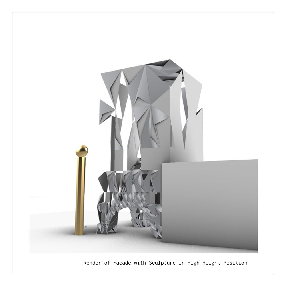
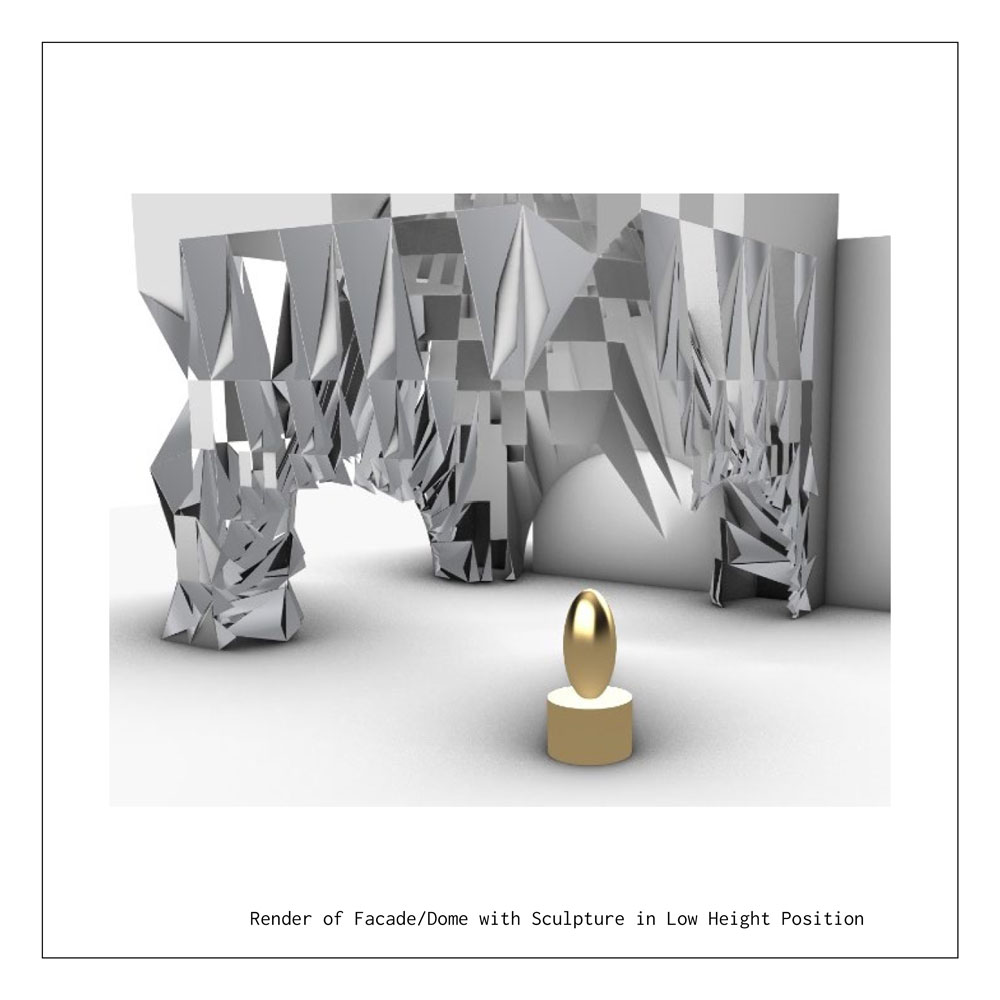
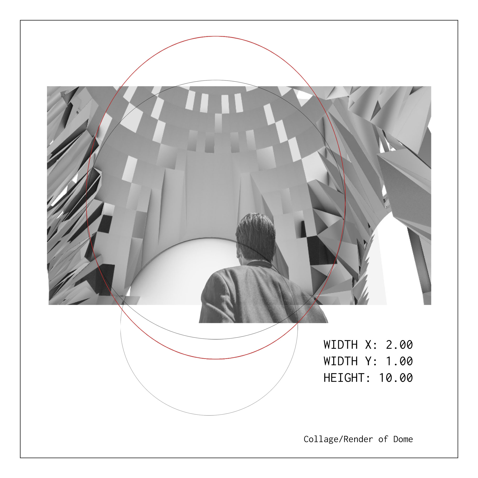
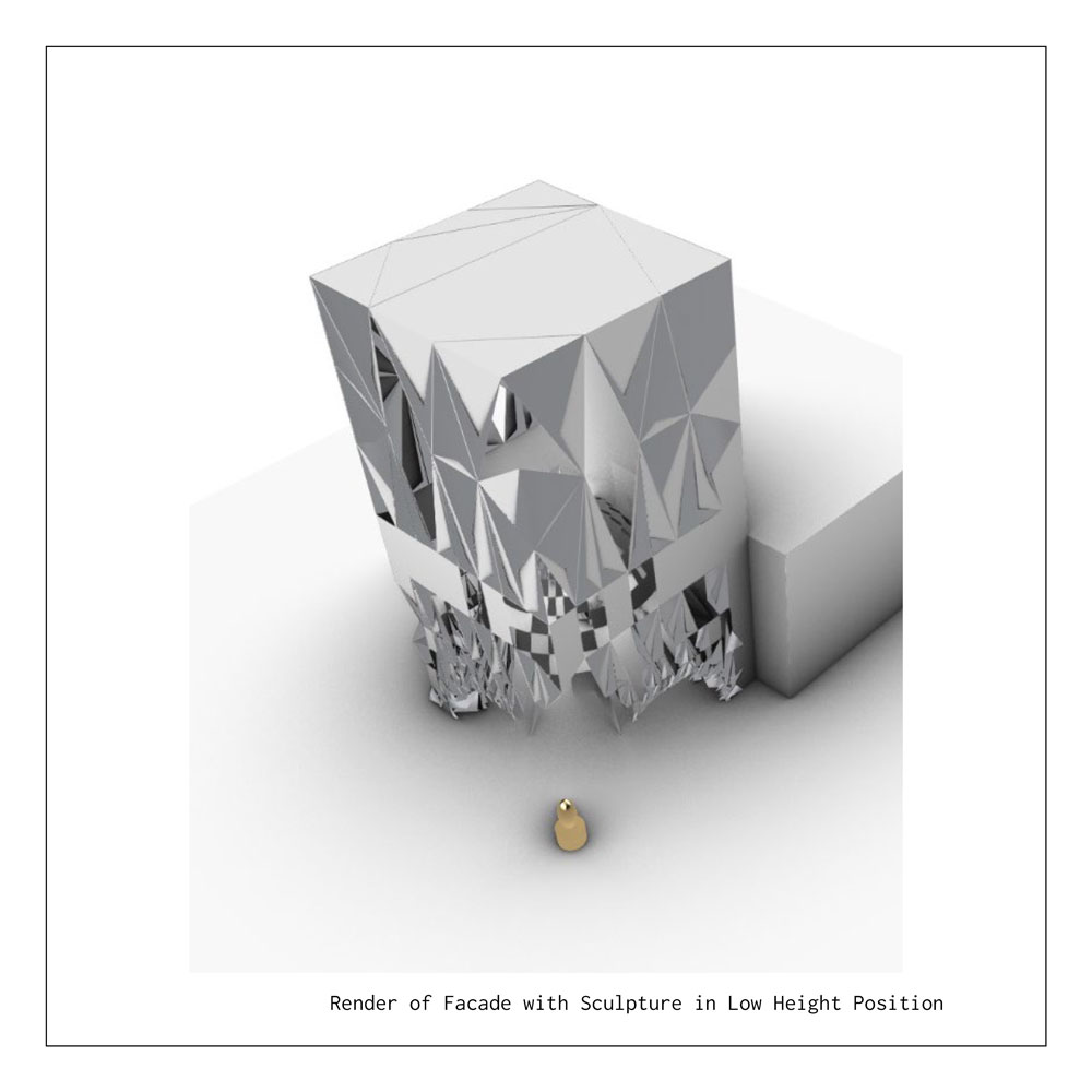
Imagining a sculpture of high importance, that was subject to change in positioning, I developed a series of C# scripts in Grasshopper to design a façade for a building. The façade design was titled “Look” for the way it commanded the interior occupants to view the sculpture and did not allow them to view the neighboring building, accounting for solidity on a shared wall. Exterior viewers have an enhanced experience of the sculpture as the building serves as a backdrop to highlight it. The façade design features an adjustable dome at the base level, allowing respite to those who chose to go outside and enjoy the sculpture.
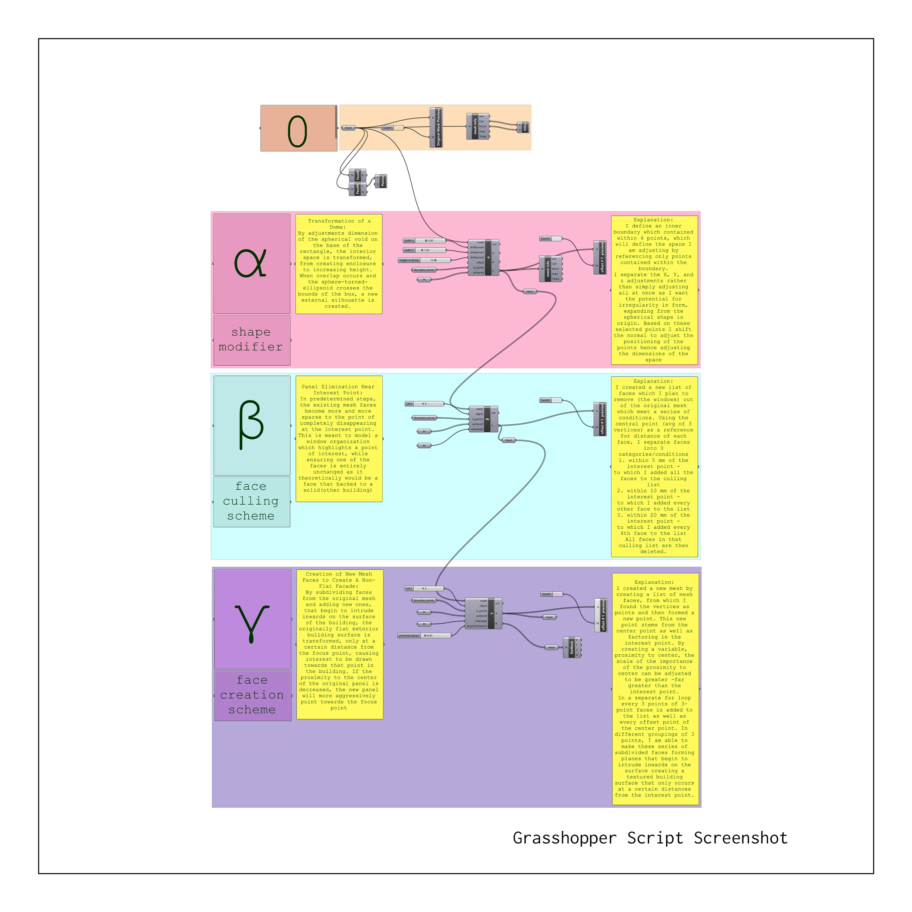
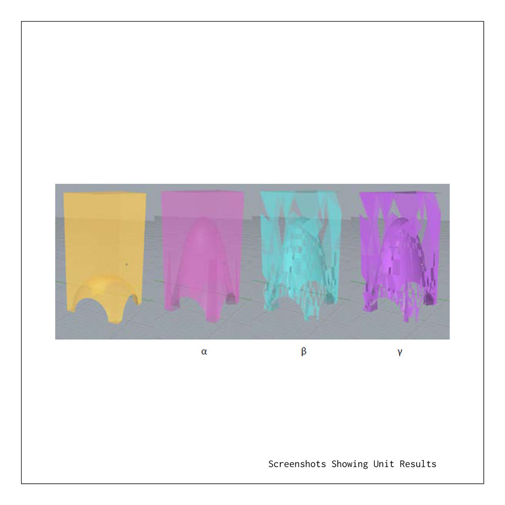
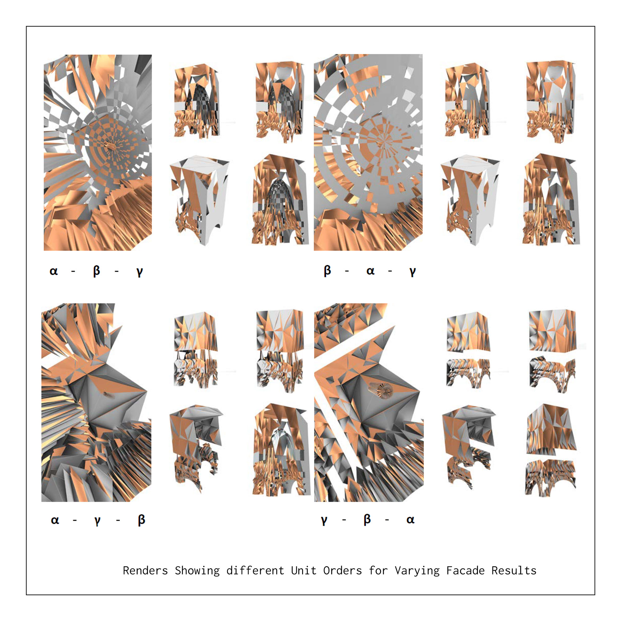
The script was assembled in 3 units, α β γ, each having their own C# script for clarity of concept. The units can be arranged in different orders for varying results.

.
Annotated Code:
List
List
double boundaryXmin = 100.0;
double boundaryYmin = 100.0;
double boundaryXmax = -100.0;
double boundaryYmax = -100.0;
foreach (Point3d bp in b_points)
{
if (bp.X < boundaryXmin) boundaryXmin = bp.X;
if (bp.X > boundaryXmax) boundaryXmax = bp.X;
if (bp.Y < boundaryYmin) boundaryYmin = bp.Y;
if (bp.Y > boundaryYmax) boundaryYmax = bp.Y;
}
//this section defines the boundary points in which the dome exists
for (int i = 0; i < mesh.Vertices.Count; ++i)
{
Point3d p = mesh.Vertices[i];
pt.Add(p);
Vector3d dp = new Vector3d(0, 0, 0);
//here the list of vertices of mesh faces and normals of those mesh faces are used to define a new distance vertex
if (p.X > boundaryXmin && p.X < boundaryXmax && p.Y > boundaryYmin && p.Y < boundaryYmax && p.Z < refptZ + 3000 && p.Z != 0)
{
Vector3d normalV = mesh.Normals[i];
dp.X = normalV.X * shiftdomeX;
dp.Y = normalV.Y * shiftdomeY;
dp.Z = normalV.Z * shiftdomeZ * -1;
}
// within those previously defined dome boundaries, the magnitude of the distance vectors is controlled by the shiftdome variables
// the shift dome variables are isolated by x, y, z in order to allow irregular movement of the dome, straying from the standard sphere
ns.Add(dp);
mesh.Vertices.SetVertex(i, p + dp);
// the new normals are now the changed distance vectors
// these normals are applied to each face in the list (within boundary points)to move the coordinate along that vertex
}
A = pt;
B = ns;
C = mesh;
{α}. The Shape Modifier
Design Intention:
Transformation of a Dome
By adjustments dimension of the spherical void on the base of the rectangle, the interior space is transformed, from creating enclosure to increasing height. When overlap occurs and the sphere-turned ellipsoid crosses the bounds of the box, a new external silhouette is created.
Explanation of Process:
I define an inner boundary which contained within 4 points, which will define the space I am adjusting by referencing only points contained within the boundary. I separate the X, Y, and z adjustments rather than simply adjusting all at once as I want the potential for irregularity in form, expanding from the spherical shape in origin. Based on these selected points I shift the normal to adjust the positioning of the points hence adjusting the dimensions of the space.
.
Annotated Code:
List
List
List
for (int i = 0; i < mesh.Faces.Count; ++i)
{
int V1 = mesh.Faces[i].A;
int V2 = mesh.Faces[i].B;
int V3 = mesh.Faces[i].C;
Point3d p1 = mesh.Vertices[V1];
Point3d p2 = mesh.Vertices[V2];
Point3d p3 = mesh.Vertices[V3];
Point3d pcen = (p1 + p2 + p3) / 3.0;
// the vertices are defined as points, which allows those points to be used to create an average to find a center point of each face
for (int i = 0; i < mesh.Vertices.Count; ++i)
// this condition ensures the deletion will only occur on faces with a central coordinate value greater than 3 in the X direction and greater than 10 in the Z direction, to avoid creating windows that would theoretically be against a neighboring building
{
double dist = pcen.DistanceTo(interestpt);
if (dist < 5)
{
cullingfaces.Add(i);
}
// if the face is within 5 mm of the interest point it will be added to the culling list
else if (dist < 10 && i % 2 == 0)
{
cullingfaces.Add(i);
}
}
//if the face is within 10 mm of the interest point, every other one (each even numbered one) will be included in the culling list
else if (dist < 19 && i % 4 == 0)
{
cullingfaces.Add(i);
}
//if the face is within 10 mm of the interest point, every 4th point will be added to the culling list.
}
// this sectioning of distances to allow categories of less deletion creates an appearance of a gradient
}
mesh.Faces.DeleteFaces(cullingfaces);
// the faces in the culling list are deleted from the mesh to create new windows
A = mesh;// the newly adjusted mesh is exported
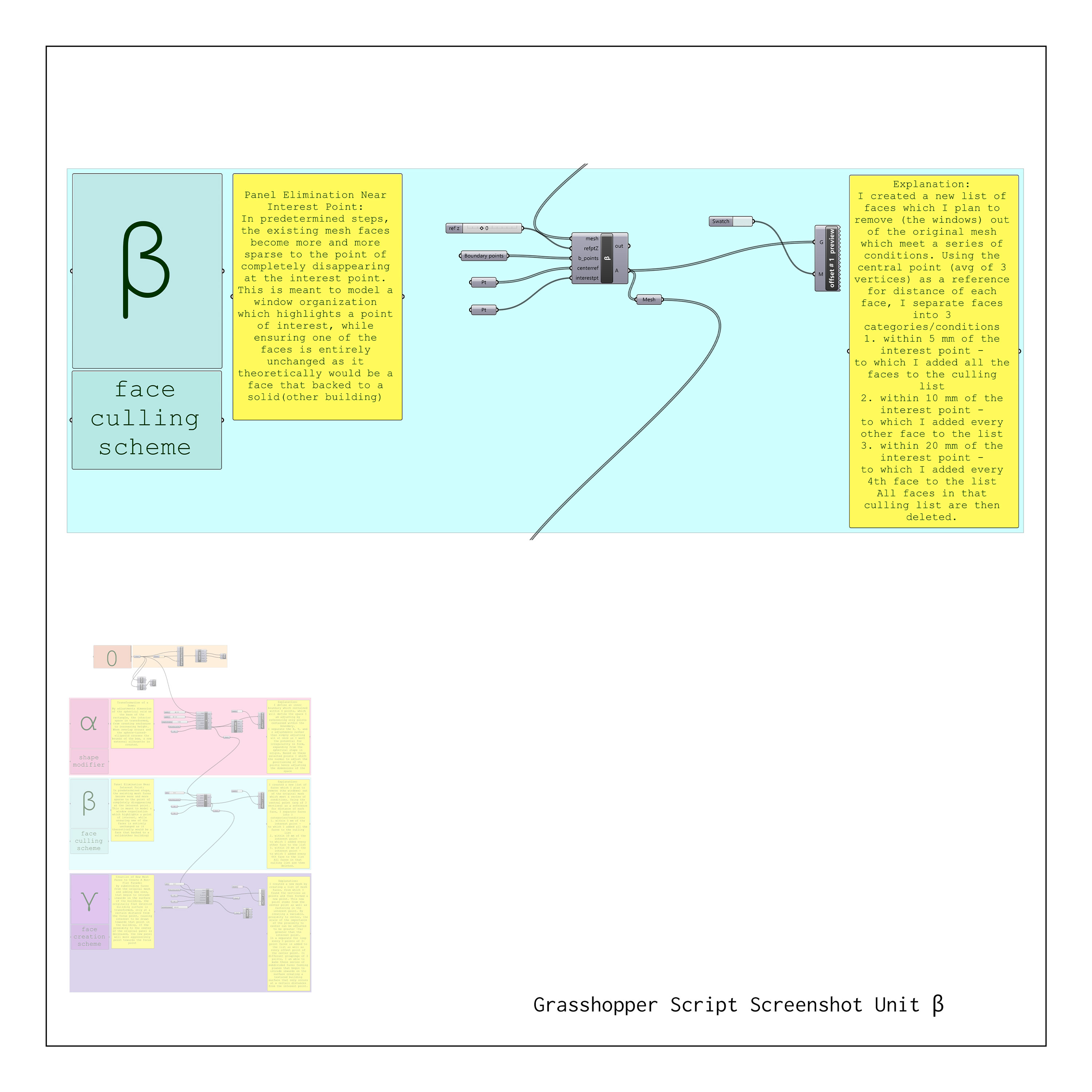
{β}. The Face Culling Scheme
Design Intention:
Panel Elimination Near Interest Point
In predetermined steps, the existing mesh faces become more and more sparse to the point of completely disappearing at the interest point. This is meant to model a window organization which highlights a point of interest, while ensuring one of the faces is entirely unchanged as it theoretically would be a face that backed to a solid (other building)
Explanation of Process:
I created a new list of faces which I plan to remove (the windows) out of the original mesh which meet a series of conditions. Using the central point (avg of 3 vertices) as a reference for distance of each face, I separate faces into 3 categories/conditions
1. within 5 mm of the interest point - to which I added all the faces to the culling list
2. within 10 mm of the interest point - to which I added every other face to the list
3. within 20 mm of the interest point - to which I added every 4th face to the list All faces in that culling list are then deleted.
Annotated Code:
List
List
List
List
Mesh newMesh = new Mesh(); // as these new panels are of a different material, they are added to the design as a new mesh rather than to the original mesh
for (int i = 0; i < mesh.Faces.Count; ++i)
{
int V1 = mesh.Faces[i].A;
int V2 = mesh.Faces[i].B;
int V3 = mesh.Faces[i].C;
Point3d p1 = mesh.Vertices[V1];
Point3d p2 = mesh.Vertices[V2];
Point3d p3 = mesh.Vertices[V3];
Point3d pcen = (p1 + p2 + p3) / 3.0;
// the vertices are defined as points, which allows those points to be used to create an average to find a center point of each face
Point3d pcenoffset = (pcen * proximitytopcen + interestpt) / (1 + proximitytopcen);
// a new point type is created, based on the center point of each face as well as the interest point.
// a new variable "proximitytopcen" controls the distance of the new point from the face by adjusting the averaging proportion (giving the original face center point a greater percentage impact than the interest point on the new point
if (pcen.X > 3)
// this condition ensures the deletion will only occur on faces with a central coordinate value greater than 3 in the X direction as to not interfere with the neighboring building
{
double dist = pcenoffset.DistanceTo(interestpt);
if (dist < 100 && dist > 0.1 && mesh.Faces[i].IsTriangle)
// here the offset point is simply required to be off the face by 0.1 mm but less than 100 (values that are somewhat arbitrary) and the faces must be triangles as the presence of rectangular faces creates issues as we only define 3 points
{
newpoints.Add(p1);
newpoints.Add(p2);
newpoints.Add(p3);
newpoints.Add(pcenoffset)
}
// the new point list is created out of the original face points as well as the new offset point.
}
}
for (int i = 0; i < newpoints.Count - 3; i = i + 4){
newMesh.Vertices.Add(newpoints[i]);
newMesh.Vertices.Add(newpoints[i + 1]);
newMesh.Vertices.Add(newpoints[i + 2]);
newMesh.Vertices.Add(newpoints[i + 3]);
// In order of how the point types were added to the list, the new point list is separated into 4 categories
newMesh.Faces.AddFace(i, i + 1, i + 3);
newMesh.Faces.AddFace(i + 1, i + 2, i + 3);
// those categories are connected in groups of 3 to define new 3 point faces on the new mesh. Specifically I only wanted 2 2 specific faces from each original face, to allow for a small opening
}
A = mesh;
// I still export the original mesh for reference
B = newMesh;
// The new mesh consists only of the additional faces created in this script
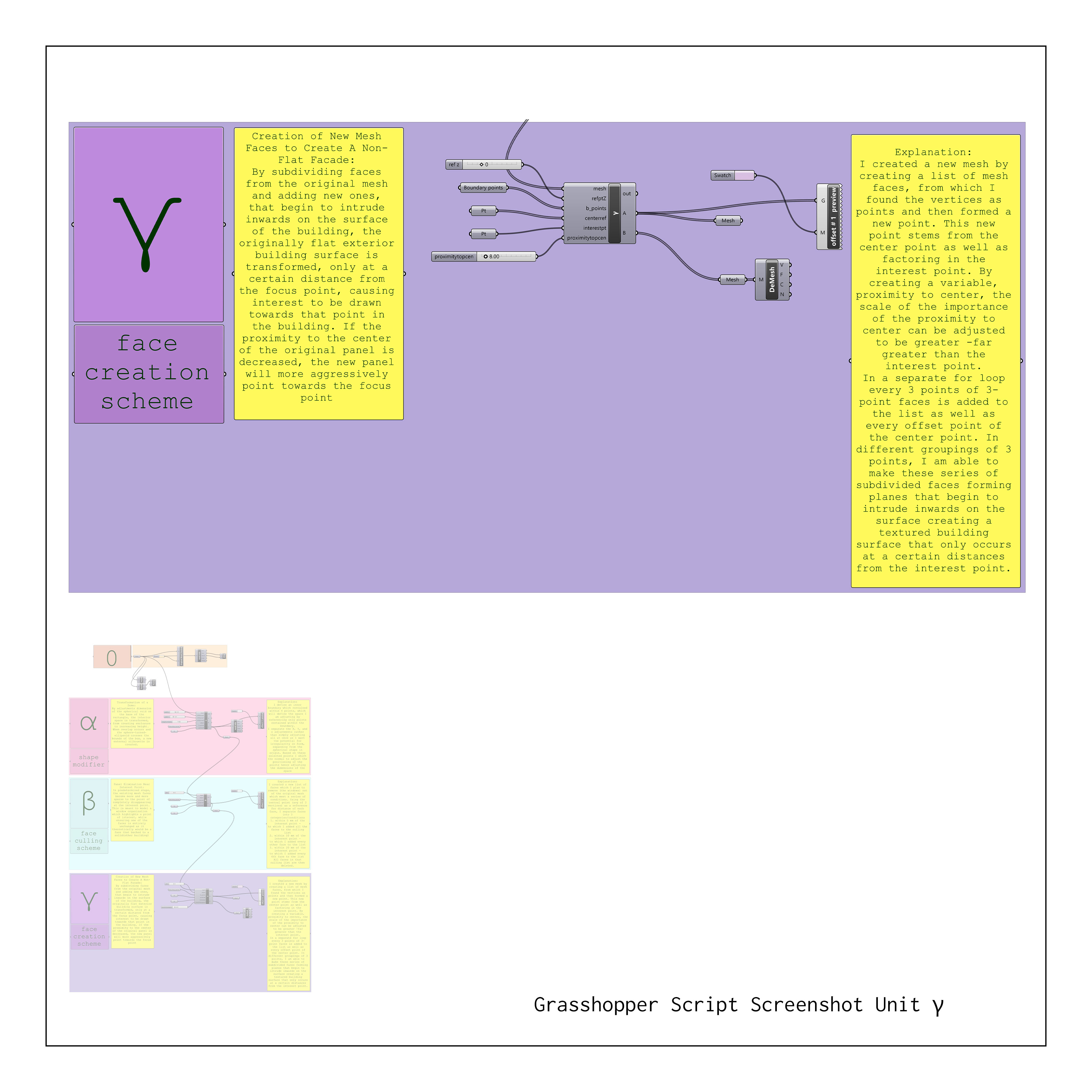
{γ}. The Face Creation Scheme
Design Intention:
Creation of New Mesh Faces to Create A Non-Flat Facade
By subdividing faces from the original mesh and adding new ones, that begin to intrude inwards on the surface of the building, the originally flat exterior building surface is transformed, only at a certain distance from the focus point, causing interest to be drawn towards that point in the building. If the proximity to the center of the original panel is decreased, the new panel will more aggressively point towards the focus point
Explanation of Process:
I created a new mesh by creating a list of mesh faces, from which I found the vertices as points and then formed a new point. This new point stems from the center point as well as factoring in the interest point. By creating a variable, proximity to center, the scale of the importance of the proximity to center can be adjusted to be greater -far greater than the interest point.
In a separate for loop every 3 points of 3-point faces is added to the list as well as every offset point of the center point. In different groupings of 3 points, I am able to make these series of subdivided faces forming planes that begin to intrude inwards on the surface creating a textured building surface that only occurs at a certain distances from the interest point.
.